Centrifugal fan design
Centrifugal fan design is usually given when the conditions are:
the volume flow rate, total pressure, the working medium and its density
(or the working medium temperature), and sometimes there are structural
requirements and special requirements.
Design requirements of a large centrifugal fan are: to meet the required flow and pressure conditions at the highest point of efficiency should be near; maximum efficiency value to be as large as some of the efficiency curve flat; pressure curve to a wide range of stability; fan of simple structure , technology is good; convenient choice of materials and accessories; have sufficient strength, stiffness, safe and reliable; running stable, low noise; adjusted performance, work adaptability; fan size as small as possible, light weight; operation and maintenance , disassemble easy transport.
However, while meeting all the requirements above, is generally not possible. In the aerodynamic performance and structural (strength, process) there are contradictions between the often, usually to seize the main contradiction solve the problem. This requires designers to choose the right design to address the principal contradiction. For example:
With the use of different fans, not the same requirement, such as public buildings used as a ventilation fan is generally used with, the most important requirement is that the general low-noise, multi-blade centrifugal fan with this feature; and require large flow The centrifugal fan is usually double-suction type; for some of the high-pressure centrifugal fan, low specific speed, the relative proportion of the leakage loss is generally larger
Fan Parts-Impeller Design
The centrifugal fans impeller have five basic blade shapes, and a number of impeller configurations (i.e) DWDI (Double width double inlet) or SWSI (Single width single inlet). The impeller design will depend on the aerodynamic duty and the operating conditions.
Blade Design

Backward inclined, backward curved blades
Backward inclined, flat plate blades
An efficient and strong shape, this design is a cost-effective alternative to the backward curved design but with flat plate blades instead of curved. This results in a slightly lower efficiency, compensated by the easier fitting of liners.
Backward inclined, forward curved blades
Also termed radial tipped blades, this design reduces the potential for dust build-up on the underside of the blades in applications with moderate amounts of gas-borne dust.
Aerofoil blades
Aerofoil
bladed impellers are most commonly used in applications handling large
volumes at low pressures. This highly efficient design of fan is used in
clean air or with gases containing small amounts of erosive particles.
Radial blades
Forming a rotor which is
essentially a large paddle wheel, this design results in a relatively
inefficient fan with a power consumption higher than that using the much
more common backward inclined blade. Its inherent mechanical strength
and resistance to wear mean it is generally used when high quantities of
abrasive dust are present in the gas stream, or when very high gas
temperatures are expected.
Single or double inlet
A double inlet impeller consists of two single inlet impellers back to back on the shaft sharing a common backplate, providing almost double the flow of a single inlet fan. The selection of a double inlet fan results in a smaller diameter, faster (and perhaps cheaper) machine compared to the single inlet alternative. Single or multiple stage
A multi-stage fan consists of two or more impellers mounted on the same shaft. The air or gas flow passes through each one in turn, with a consequent increase in pressure
 |
| MAJOR CENTRIFUGAL FAN PARTS |
Design requirements of a large centrifugal fan are: to meet the required flow and pressure conditions at the highest point of efficiency should be near; maximum efficiency value to be as large as some of the efficiency curve flat; pressure curve to a wide range of stability; fan of simple structure , technology is good; convenient choice of materials and accessories; have sufficient strength, stiffness, safe and reliable; running stable, low noise; adjusted performance, work adaptability; fan size as small as possible, light weight; operation and maintenance , disassemble easy transport.
However, while meeting all the requirements above, is generally not possible. In the aerodynamic performance and structural (strength, process) there are contradictions between the often, usually to seize the main contradiction solve the problem. This requires designers to choose the right design to address the principal contradiction. For example:
With the use of different fans, not the same requirement, such as public buildings used as a ventilation fan is generally used with, the most important requirement is that the general low-noise, multi-blade centrifugal fan with this feature; and require large flow The centrifugal fan is usually double-suction type; for some of the high-pressure centrifugal fan, low specific speed, the relative proportion of the leakage loss is generally larger
Fan Parts-Impeller Design
The centrifugal fans impeller have five basic blade shapes, and a number of impeller configurations (i.e) DWDI (Double width double inlet) or SWSI (Single width single inlet). The impeller design will depend on the aerodynamic duty and the operating conditions.
 |
| TYPES OF BLADE DESIGN |
Backward inclined, backward curved blades
 |
| 3D MODEL OF BACKWARD CURVED IMPELLER |
A
highly efficient design of impeller. Its inherent strength means that in
addition to handling air, it can be used with gases containing moderate
amounts of erosive particles and at high temperatures. It can carry
liners and hard surfacing, if required.
An efficient and strong shape, this design is a cost-effective alternative to the backward curved design but with flat plate blades instead of curved. This results in a slightly lower efficiency, compensated by the easier fitting of liners.
Backward inclined, forward curved blades
Also termed radial tipped blades, this design reduces the potential for dust build-up on the underside of the blades in applications with moderate amounts of gas-borne dust.
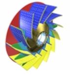
 |
| 3D MODEL OF AEROFOIL IMPELLER |
Radial blades
 |
| 3D MODEL OF RADIAL TIP IMPELLER |
Impeller configurations
Single or double inletA double inlet impeller consists of two single inlet impellers back to back on the shaft sharing a common backplate, providing almost double the flow of a single inlet fan. The selection of a double inlet fan results in a smaller diameter, faster (and perhaps cheaper) machine compared to the single inlet alternative. Single or multiple stage
A multi-stage fan consists of two or more impellers mounted on the same shaft. The air or gas flow passes through each one in turn, with a consequent increase in pressure